Route planning overview
Overview
When clicking on "Plan a new route" (or editing an existing route), the route planner will open, where routes can be created, imported or edited.
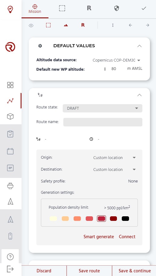
The following features are described from top to bottom and left to right.
Module selector
There are five icons representing, from left to right, the different modules of the menu: "Mission", "Geocages" , "Rally", "Safety" and "Checks". The module selected will have its name shown and its colour will turn to red.
Show/hide elements
"Show/hide elements" allow to show/hide different elements of the routes and the screen. A red icon represents a shown element, while a grey icon represents a hidden element. From left to right, the different elements are:
- Show/hide VLOS area: a white translucid circle around the operator showing the region in which he has visibility and where VLOS conditions could be considered. By default, the radius of this circle is 1000 m.
- Show/hide geocages: geocages and other areas/volumes. Geocages include: geocage, pregeocage, ground buffer and generic polygons. See Geocages.
- Show/hide altitude profile: the altitude profile shows the flight plan profile and compares it with the ground level. See Mission.
- Show/hide rally points: rally points are safety points towards which the drone could go automatically in case of contingencies or emergencies when the UAS is too far from the takeoff or landing points. See Rally Points.
Quick edition tools
"Quick edition tools" are different tools that allow to quickly edit the route. From left to right, the icons are:
- Set or increase point altitude: modifies the altitude of all the waypoints at once. See Set altitude.
- Undo action: undoes the last action. It should be noted that, since waypoint edition requires the system to do multiple calculations of the ground level, this action might take a few seconds.
- Forward: redoes undone actions. It should be noted that, since waypoint edition requires the system to do multiple calculations of the ground level, this action might take a few seconds.
Default values
Default vaules provide information on altitude data source
- Show/hide Default Values: shows/hides default values (altitude data source, default altitude for new waypoints and altitude frame).
- Altitude data source: allows to change the altitude data source for the terrain. Available sources are:
- Copernicus COP-DEM30
- Google Elevation API
- Luxembourg DEM (if enabled in the project)
- Disclaimer:
- The altitude data sources do not include artificial and natural obstacles.
- The operator shall consult with their competent authority what sources are acceptable to ensure proper obstacle avoidance.
- The operator shall evaluate the presence of obstacles in their operational volume and plan operations accordingly.
- RigiTech is not responsible for any decision taken by the operator due to the interpretation of the altitude data.
- Altitude default values: allows to set the default altitude for new waypoints. The altitude frame is "AMSL - Altitude above sea level".
- By default, 80 m above the terrain calculated for the first waypoint (Takeoff), in AMSL.
Route information
Within the route information, the name, state and estimated distances and times are available. This section also includes tools for automatic route generation.
- Show/hide route information
- Route state: allows to change the sate of the route (Draft, Validated and Approved). See Route state.
- Name editor allows to name or edit the name of the route. When saving a nameless route, it will named automatically based on the date and time of the first saving.
- Route information: from left to right, estimated flight distance of the route and estimated time of the flight. It should be noted that the estimated distance and time do not need to match with the actual distances/time flown by the UAS during an operation due to possible deviations, sharp turns, wind, etc.
- Origin and destination for automatic generation: allows to set the origin and destination (waypoints, bases and/or markers) to automatically generate a flight plan through the available tools (smart generation and connection). Origins/destinations can be selected by clicking on the down arrow and selecting a location in the list that will open. This list contains all the markers and bases of the project. If no location is selected, the default location will be "Custom location", which allows to create a flight plan based on the current first and last waypoints.
- Safety profile: indicates which safety profile is defined for this route.
- Generation settings: allows to define the maximum population density over which the drone can fly when using the "Smart generate" feature. See more details in the Smart generate section.
- Smart generate: allows to automatically generate a flight plan between two points. See Smart generate.
- Connect: allows to automatically generate a simple connection between two points. See Connect.
- List of waypoints: shows the list of waypoints added to the route (empty at the creation of a new route).
Import flight plan
Existing flight plans can be imported by dropping the file in this area or by clicking on it an browsing the file from the computer.
Discard/save route
- "Discard": cancels all the changes done since the last time the route was saved.
- "Save route": saves the route (which is not possible if the route has not been named or if there are errors) and leaves the editor. It is recommended to save the route periodically to avoid losing information.
- "Save & continue": saves the route and continues in the editor.
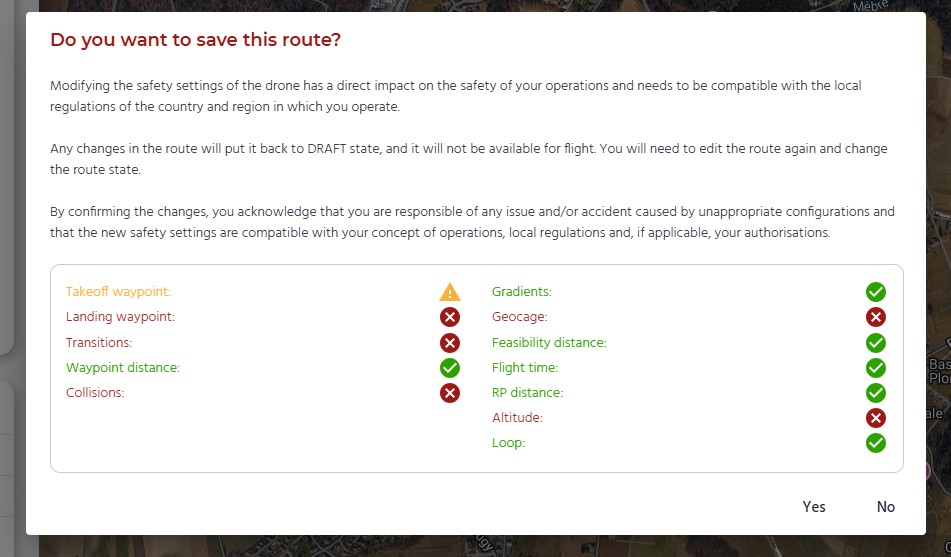
When saving clicking on "Save route", a window will pop up showing the safety checks of the route, as well as a request to confirm the saving of the route. It is the operator's responsibility to confirm the modifications under the conditions of the flight plan.
Route state
Route states have multiple purposes:
- Allows to order/filter routes by their state (in the "Route" menu).
- Allows to prevent modifications on approved/validated routes by unauthorized users.
- Allows to prevent non approved routes to be uploaded to the UAS.
Only Head of Operations users can modify the status of the route and modify "Validated" or "Approved" routes.
There are three route states available:
- Draft: default route state.
- Any new, cloned or reversed will start with this status.
- Modified routes will become "Draft" automatically.
- "Draft" routes cannot be uploaded to UAS.
- "Draft" routes can be uploaded to simulators.
- The purpose of this state is to show routes that are in an early stage and have not been validated.
- Validated:
- "Validated" routes cannot be uploaded to a UAS.
- "Validated" routes can be uploaded to simulators.
- The purpose of this state is to show routes that have been validated internally, but that have not been approved by the authorities (or, if not required, by the Head of Operations).
- Approved:
- "Approved" routes are the only routes that can be uploaded to a UAS.
- "Approved" routes can be uploaded to simulators.
- The purpose of this state is to show routes that can be operated and should not be modified.
Set altitude
There are specific tools to set or increase the altitude of all the waypoints at once.
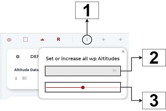
- Set altitude: makes the window of the tool to pop up.
- Set an altitude for all the waypoints: sets an altitude for all the waypoints.
- Increase/decrease all the waypoints altitudes: modifies the altitude of all the waypoints by increasing/decreasing them a constant number with the the scrolling bar.
Use of markers for origin and destination
Markers should be used to define precise takeoff and landing locations (based on the drone's measured GNSS coordinates). This is particularly important when using RTK.
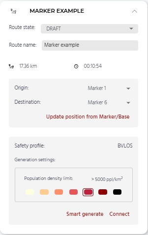
By clicking on "Custom location" next to Origin and Destination will open the list of markers and bases. After planning tha takeoff and landing waypoints on the map, when selecting one (or both), the button "Update position from Marker/Base" will be displayed.
By clicking on it, the following waypoint coordinates will be updated:
- Takeoff (as per the marker/base defined for the Origin)
- Landing (as per the marker/base defined for the Base)
To properly support RTK, this procedure requires that the markers/base coordinates have been set at the drone's position, as described in Bases, markers and routes.
Smart generate
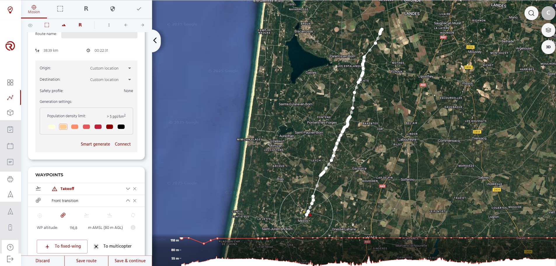
The Smart generate tool allows to quickly generate a complete route between two locations or waypoints. The route is generated in such a way that the first waypoint and the last waypoint (or the origin and destination) are set as the takeoff and landing waypoints, with transition waypoints just after/before them, and a series of waypoints between them, generated automatically by taking into account the terrain profile and, if applicable, the geocages.
The user can also select a maximum population density over which the drone can fly. The Smart Generate algorithm will then automatically generate an entire route based on the population density, terrain and geocages.
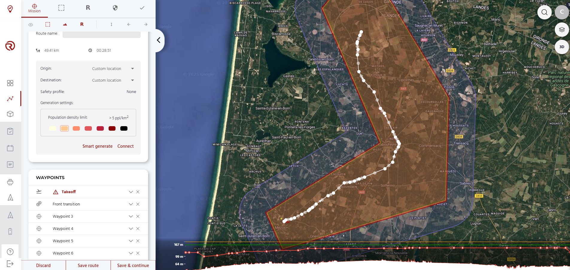
In the examples below, two automatically generated flight plans are presented. In the first one, the flight plan is generated based only on the elevation and the capabilities of the drone. In the second one, a group of geocages were defined before the generation of the flight plan. Therefore, the automatically generated flight plan has selected the best path in terms of the elevation and the capabilities of the UAS within the available space.
It should be noted that to smartly generate flight plans within geocages, the latter must be wide enough to allow turns, climbings, descents, etc.
Disclaimer:
- Although the flight plans generated take into account certain restrictions, such as the feasible gradients of the drones, the elevation and the geocage, it is the operator's responsibility to ensure that:
- The flight plan is within the capabilities of the drone;
- There are no obstacles in the trajectory of the drone;
- The flight plan does not violate local regulations and/or restrictions.
Connect
The connect tool allows to quickly connect two locations (based on a base or a marker), by creating a route with four waypoints and the first safety profile available.
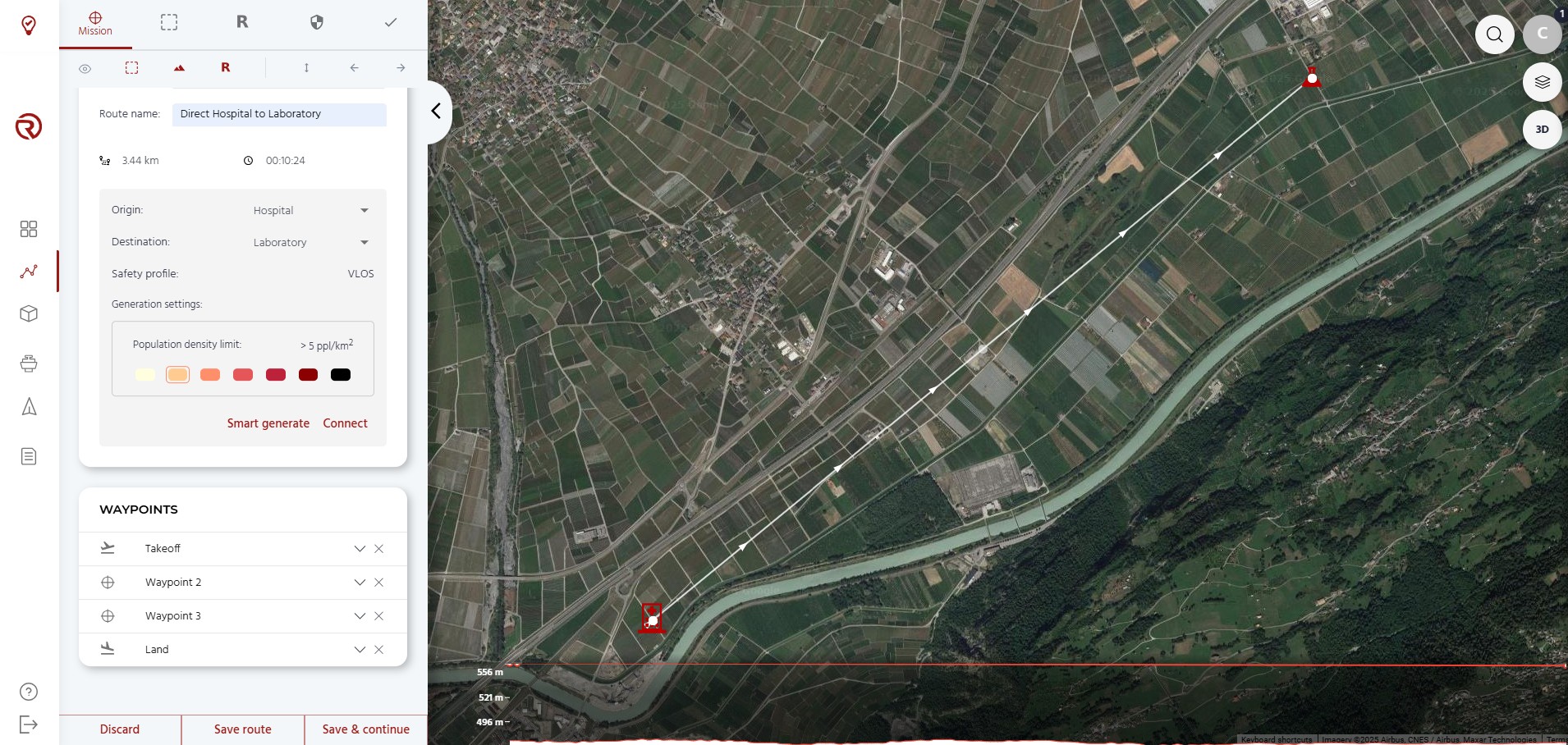
It should be noted that this flight plan shall not be used in real flights.