Mission
Overview
Within the "Routes" module, the "Mission" menu allows to prepare the flight plan by adding/removing/editing waypoints, the main elements of a route.
Waypoints can be added by simply clicking on the desired location in the map. "Intermediary waypoints" can become new waypoints by clicking on "middle points" (transparent circles between waypoints) and dragging them.
Their position can be edited by clicking on them and dragging them to the new position. Their coordinates can also be edited manually by opening a waypoint's information and changing the numerical values of the coordinates.
Finally, waypoints can be removed by clicking on "Remove" in the waypoints menu or by right-clicking on them on the map an selecting "Delete".
On the map, the following elements of the flight plan are represented:
- Waypoints: white circles.
- Waypoint with warnings: warning symbol next to the waypoint.
- Intermediary waypoints: white semi-transparent circles.
- Flight path: white line connecting waypoints.
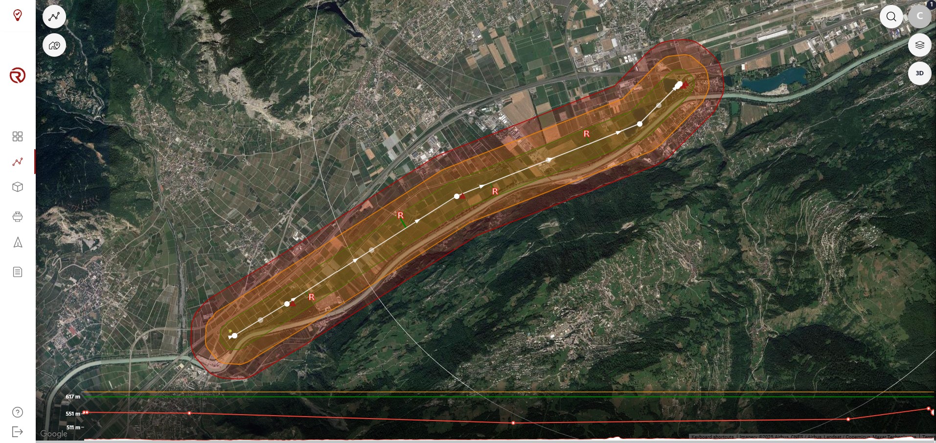
- Geocages: areas or circles with different colours. See Geocages.
- Rally points: red "R". See Rally Points.
- Altitude graph: as long as it is shown (third show/hide element under the module selector), the altitude graph displays the vertical profile of the operation. See Operation structure.
See Operation structure for more information on how to properly set an operation in terms of distances, altitudes, radii, etc.
Waypoints menu
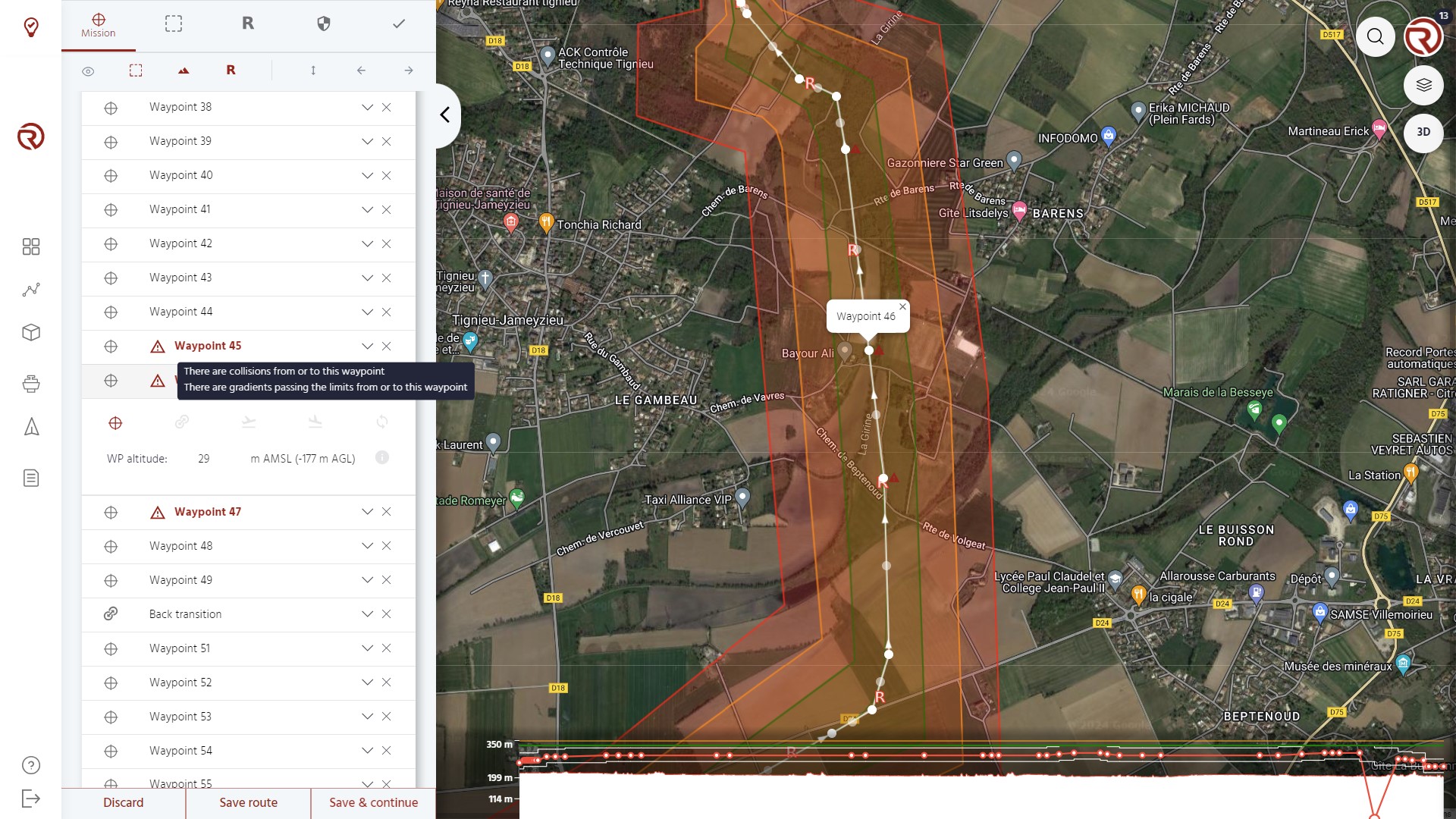
Under "WAYPOINTS", waypoints can be edited (altitude and type) and configured/removed. Their detailled information is also available.
- Waypoints: from left to right, icon of the waypoint (which depend on its type), name and, eventually, its number (if it is a regular waypoint).
- Expand waypoint: expand one waypoint and displays its type, altitude (in AMSL and AGL) and additional information icon. Altitudes can be edited only in AMSL, but information in AGL is visible.
- Remove waypoint
- Waypoint type: allows to change the type of the waypoint. The selected type of waypoint is highlighted in red. From left to right, the different waypoints are:
- Waypoint
- Transition
- Takeoff
- Land
- Drop payload
- Only if enabled for the UA.
- Loop
- Altitude: all the waypoint types allow to select at least one altitude. For regular waypoints, transitions and loops, "WP altitude" represents the altitude at which the UA will aim to fly.
- Show/hide waypoint information
- Waypoint information: includes relevant information of the waypoint compared to the terrain and other waypoints. From left to right and top to bottom:
- Latitude (can be edited manually)
- Longitude (can be edited manually)
- Ground leavel
- Heading
- Distance to the previous waypoint
- Distance to the next waypoint
- Altitude difference with the previous waypoint
- Altitude difference with the next difference
- Gradient with previous waypoint
- Gradient with next waypoint
Waypoint
Generic waypoints are the points aimed by the UA when flying. They are the main element of the flight plan.

Transition
When clicking on "Transition" on a given waypoint, a new selector will open, allowing to choose between a "To fixed-wing" waypoint (Front transition) and a "To multicopter" waypoint (Back transition).
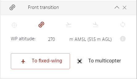
- By default, the first transition point created will be a "To fixed-wing" one (Front transition), while the second, as long as the waypoint is after the first one, will be a "To multicopter" point (Back transition). Users shall confirm that they are in the correct order.
- A front transition starts at the "To fixed-wing" point and aims to end before the next waypoint.
- A back transition point starts before this point and aims to end no later than this point. If this was not possible, an overshoot might happen.
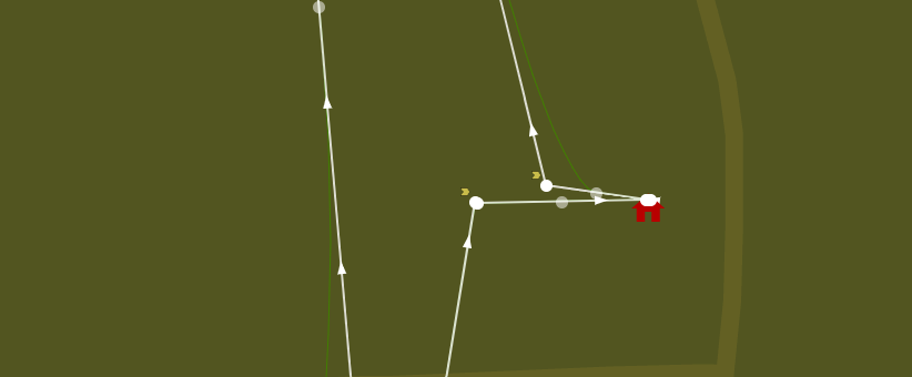
- Transition points are marked with small yellow arrows next to the white circles.
- Users may plan multiple sets of transitions. It is their responsibility to ensure that all transitions have the correct order and are planned properly.
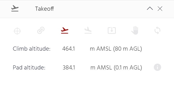
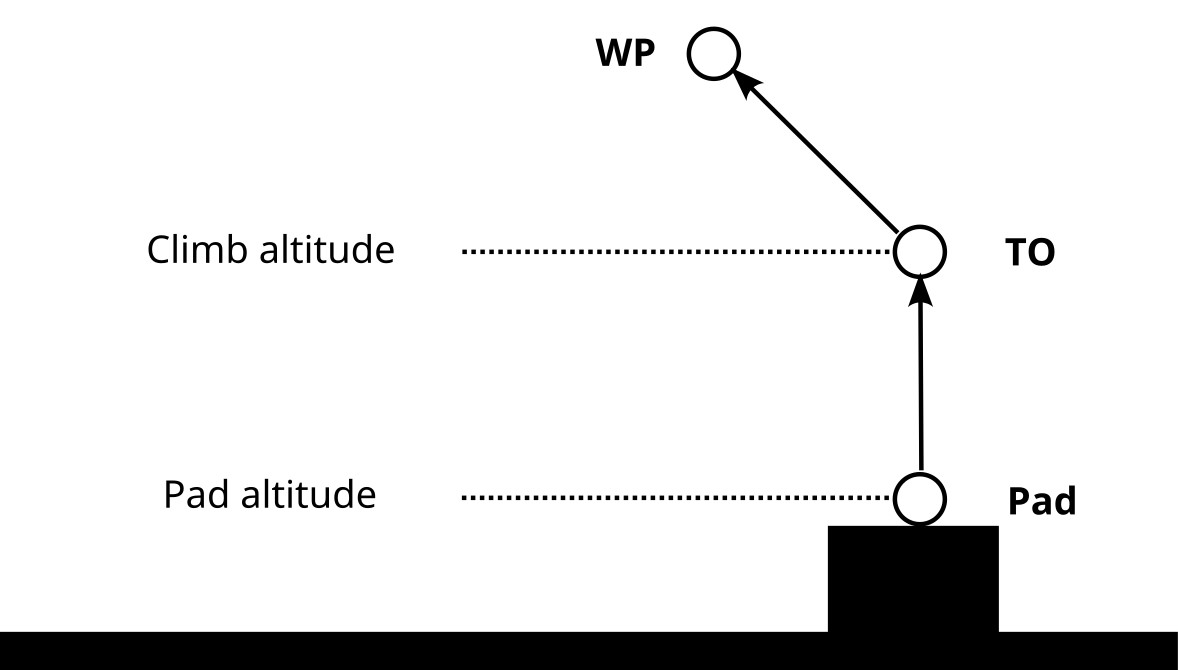
Takeoff
By default, the first waypoint created is a "Takeoff" point (TO).
- The UA arms, starts to spin the motors and will takeoff and climb in multicopter configuration up to the selected altitude (Climb altitude) and go to the next waypoints (WP).
- "Pad altitude" represents the altitude where the UA starts spinning its motors from ground (where the Precision Pad would be located, if any). This altitude may be different from the ground level (e.g. takeoff from a roof or structure, terrain model resolution, etc.).
Note: If the pad altitude is below the measured ground altitude, a warning will be displayed. However, this will not block the flight plan from being saved and/or uploaded to the UA.
The coordinates of the Takeoff point should be updated based on a marker position, as defined in Route planning overview.
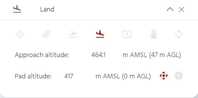
Land
The "Land" point (LD) must be the last waypoint of the list.
- It must be put in a section of the route in which the UA is set to fly in multicopter configuration from the previous waypoints (WP).
- The UA will reach the landing location at the specified altitude (Approach altitude), and then will descend until it detects the ground, stop spinning the motors and disarm.
- "Pad altitude" represents the altitude where the UA stops spinning its motors after having touched the ground (where the Precision Pad would be located, if any). This altitude may be different from the ground level (e.g. landing on a roof or structure, terrain model resolution, etc.).
If there is a Precision Pad, enabling the "Precision landing" option will make the UA look for the Precision Pad.

Note: If the pad altitude is below the measured ground altitude, a warning will be displayed. However, this will not block the flight plan from being saved and/or uploaded to the UA.
The coordinates of the Land waypoint should be updated based on a marker position, as defined in Route planning overview.
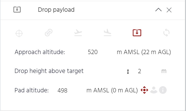
Drop payload
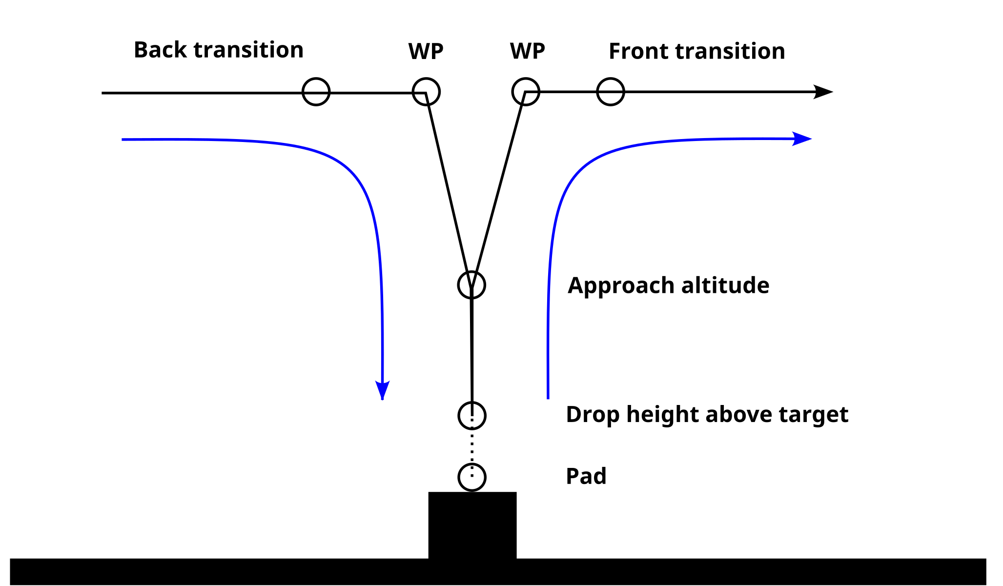
The "Drop payload" point allows the UA to drop its payload at a selected height above the ground. The sequence starts once the UA reaches the location of the "Drop payload" point at the "Approach altitude". The UA will then use the precision sensor selected (downwards facing camera and Precision Pad or lidar) to descend to the "Drop height above target". If the precision sensor is not available (Precision Pad not detected or lidar not in range), the "Drop payload" point is skipped. Once the "Drop height above target" is reached for 2 seconds, the payload is dropped and the UA will climb back to the "Approach altitude".
Drop payload point horizontal structure:
- The "Drop payload" point is skipped if it is not reached in multicopter configuration.
- It is recommended to have one waypoint between the Back Transition and the Drop payload points, and another waypoint between the Drop and Front Transition points.
Drop payload point vertical structure:
- "Approach altitude": altitude at which the drone will start using the precision sensor to navigate towards the payload drop zone. It ust be between 20 and 25 m above the "Pad altitude" to maximize the chances of having a valid precision sensor i.e. Precision Pad detected or lidar in range.
- "Drop height above target": height above the "Pad altitude" at which the payload is dropped. It must be set between 2 and 10 m.
- "Pad altitude": altitude of the Precision Pad (or the ground when using the lidar as precision sensor). This altitude may be different from the ground level displayed in cloud (e.g. landing on a roof or structure, terrain model resolution, etc.).
Selection of precision sensor:
- "Drop with target": The UA will use the downwards facing cameras and the Precision Pad to navigate towards the drop zone. The UA will correct horizontally to attempt to drop on the Precision Pad.
- "Drop with lidar": The UA uses the lidar to descend to the drop height. The UA will not correct horizontally.
- At least one of the previous options must be chosen.
Notes:
- If the pad altitude is below the measured ground altitude, a warning will be displayed. However, this will not block the flight plan from being saved and/or uploaded to the UA.
- The "Drop payload" point is only available for UAs with a dropping mechanism.
Loop
Although loops are generally not required in long-range delivery routes, they are frequently used for flight testing and training.
In order to prepare a loop, within the "Mission" menu, after expanding the waypoint of the list in which the loop is desired, the "Loop" type of waypoint shall be selected.
When clicking on "Loop" in a given waypoint (origin of the loop), a new selector will open, allowing to configure the loop.
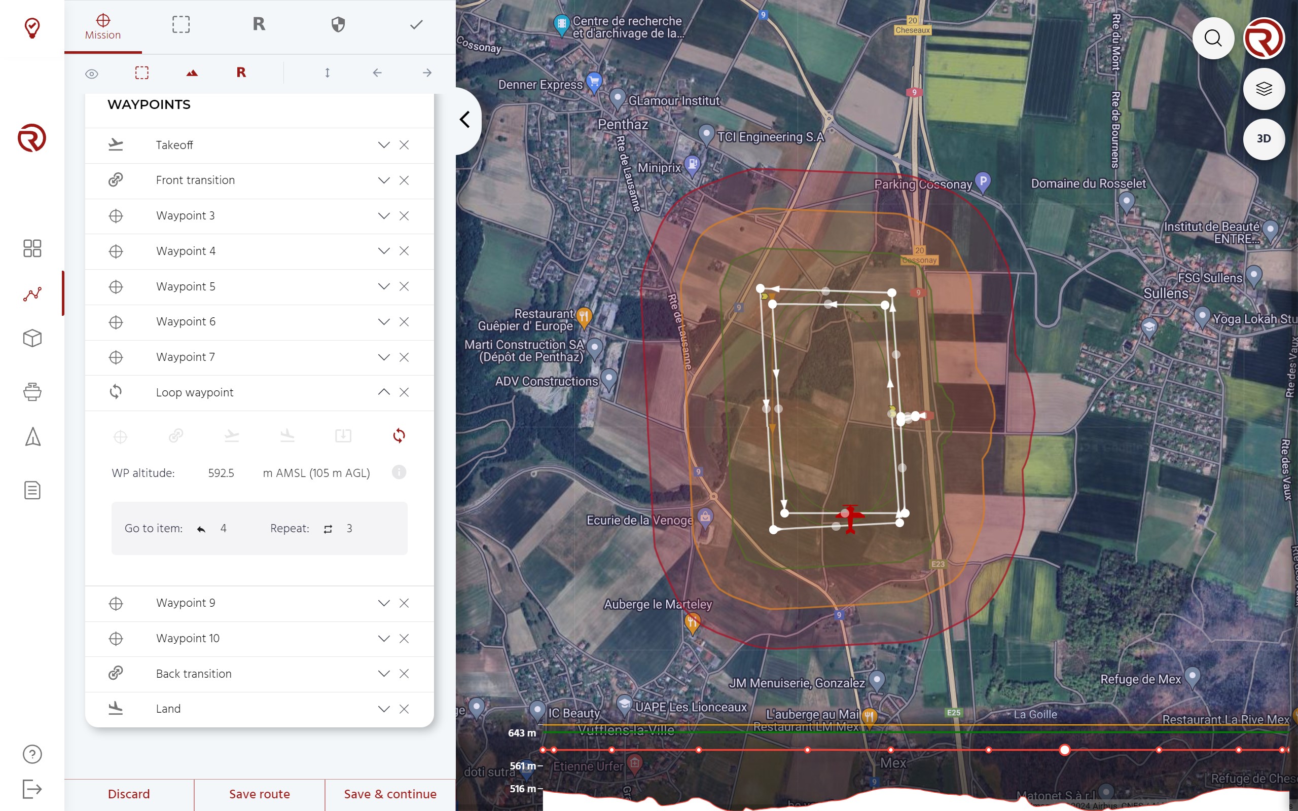
- Example of loop waypoint (within the waypoint list)
- Go to item: waypoint at which the drone should go. The number refers to the position of the waypoint/point in the list.
- Repeat: number of repetitions of the loop.
- Example of loop (within the map): an orange line with arrows shows the path followed during the loop, from the origin to the destintation of the loop.
- Example of origin of a loop: loop points (origins) are marked with small yellow arrows next to the white circles.
- Example of destination of a loop
The loop is defined by the starting waypoint, which is the waypoint where the loop is selected. The next waypoint of the loop is the one selected in "Go to item". The path flown by the UA in the context of the loop is represented by an orange arrow that goes from the first waypoint and the waypoint selected in "Go to item".
In the picture, the flight plan has the following structure.
| Item | Identification |
|---|---|
| 1 | Takeoff |
| 2 | VTOL front trans (waypoint 2) |
| 3 | Waypoint 3 |
| 4 | Waypoint 4 |
| 5 | Waypoint 5 |
| 6 | Waypoint 6 |
| 7 | Waypoint 7 |
| 8 | Loop to item 4 (waypoint 8) |
| - | Waypoints 5 to 8 (3 times) |
| 9 | Waypoint 9 |
| ... | ... |
Additional notes:
- When a loop is prepared, the turns should not be too sharp and that the altitudes between the first waypoint of the loop and item towards the UA "goes" should respect the limit gradients of the UA.
- The destination of a loop should be a regular waypoint.
- Within the loop, no special waypoints should be used (takeoff, land, transition or other loops).
Warnings
Both within the waypoint list and the map when a waypoint or a set of waypoints do not pass the safety checks, a warning will be displayed next to it.
When hovering over the warning icon in the waypoints list, the issue of that waypoint will be displayed.